Charlie Reynolds
Breadboards
In our first lab I learned about the use of breadboards and how they are set up. Breadboards are reusable construction bases for testing electronics. There are two columns (that aren’t connected) along the breadboard each with a positive (red: voltage supply) and negative (blue: ground). The middle of the breadboard provides connectors between the positive and negative columns allowing for current to flow. Once a power source is connected to a +/- column (9V battery), you can start connecting components into a circuit. Once you connect components together, they should end up connected to the – column to complete the circuit.
Multimeters
We tested our circuits and batteries with multimeters during Lab 1. Multimeters allow you take electronic measurements whether it be current, voltage, or resistance. They are helpful for checking if the circuit is connected and to measure how electricity is flowing. This can help to troubleshoot any problems in the circuit. Also, they come in handy when you want to check the voltage of a battery or the resistance of a resistor.
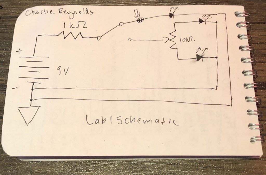
Analog Circuit Troubleshooting
- Connected an LED’s short end into the positive column on accident and it exploded
- Face the potentiometer towards the LED’s for correct orientation
- One column of the breadboard does not connect to the other column on the other side
- Make sure connecting wire/resistor is connected to the middle prong of potentiometers, switches, etc.
- Remember to connect a component to ground if the circuit does not connect back
- Make sure wire is long enough to enter the breadboard
Final Projects
Sean Porio: I enjoyed the design of Sean’s guitar pedal. It has multiple features a few of which are just controlled by a switch. He was able to make octave, distortion, input gain, and low pass filter effects all in one unit.
Jake Sandalsky: I like that Jake configured a synth clarinet with playable notes. He very clearly explains his process of how he made everything. I hope to design a project with oscillators in it, so this will be a helpful reference. I like how clean the circuits are and hope to have a project that looks easy to follow.
Ryan Mahany: I enjoy how he utilized the photocell and LED to change the speed of the tremolo. It is was easy to understand the two different paths of the effect in his schematics. I enjoy that he utilized an envelope follower to eliminate negative signal.
